
- MM3 MODCHIP SCPH 5501 DIAGRAM HOW TO
- MM3 MODCHIP SCPH 5501 DIAGRAM MOD
- MM3 MODCHIP SCPH 5501 DIAGRAM SERIAL
- MM3 MODCHIP SCPH 5501 DIAGRAM CODE
- MM3 MODCHIP SCPH 5501 DIAGRAM SERIES
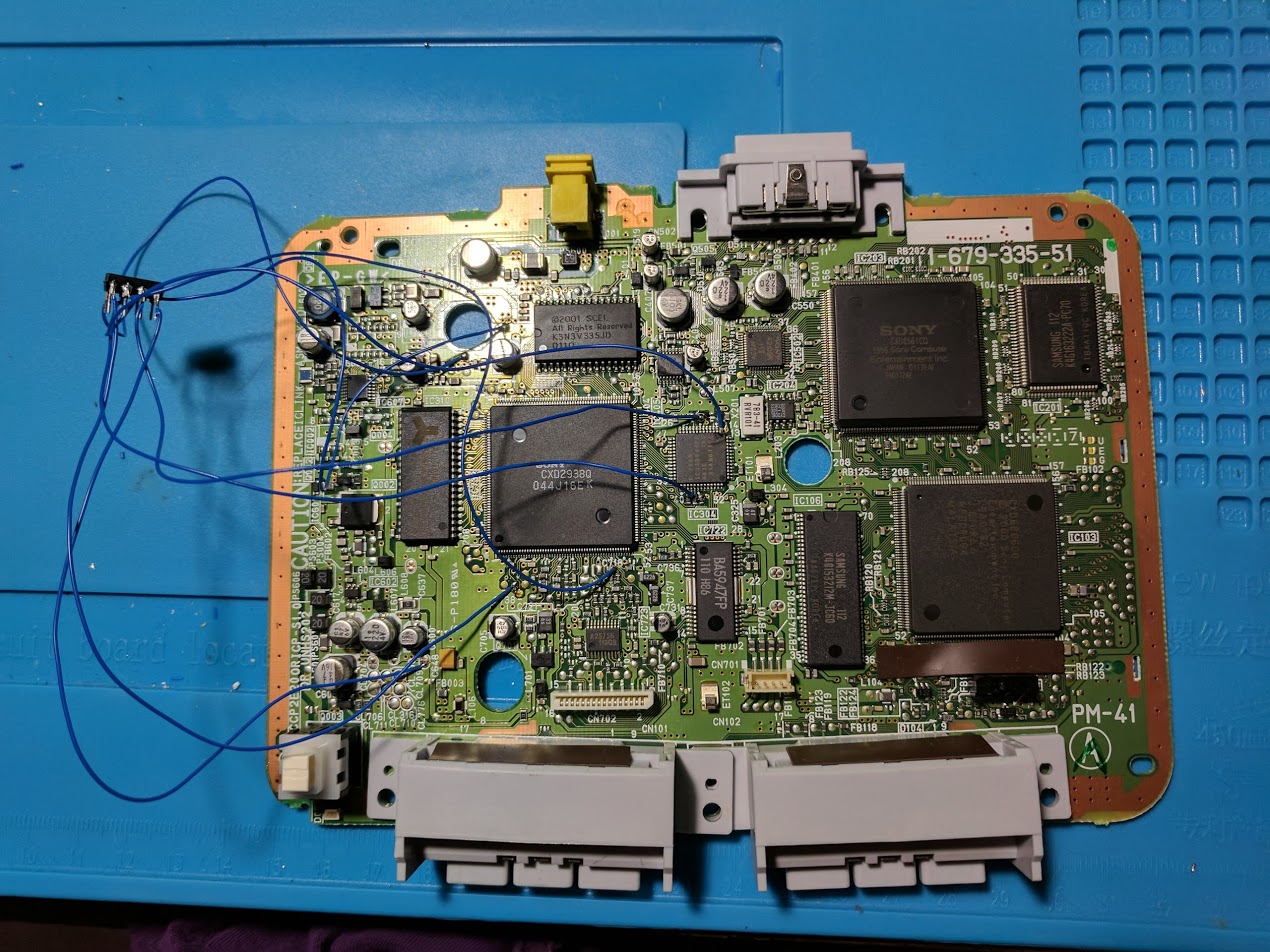
I used some alternative points for the power and ground connections (pins 1 and 8) for a cleaner installation. Here is an installation I have done on a PU-23 board. They also shrunk down the size of the board significantly.
MM3 MODCHIP SCPH 5501 DIAGRAM SERIES
The most notable difference between the 9000 series and earlier consoles is that Sony removed the parallel IO port on the back. Most of these consoles have PU-23 boards inside. This is a similar post, but covering anSCPH-7501 PlayStation 1 MM3 modchip installation. The last version of the original PlayStation 1 design was the SCPH-900x.
MM3 MODCHIP SCPH 5501 DIAGRAM HOW TO
This section has photos of some successful installations which you can use to get a better understanding of how everything is wired and positioned. SCPH-7501 PlayStation 1 MM3 modchip installation (PU-22 NTSC board) In April I wrote a post on how to install a MM3 modchip into a PM-41 NTSC PSone console.
MM3 MODCHIP SCPH 5501 DIAGRAM MOD
Older models of the Playstation are easier to mod since newer models (SCPH-9001 & PSOne) require you to solder onto surface-mount capacitors, which can become dislodged when attempting to solder to them, more than likely causing irreparable damage.
MM3 MODCHIP SCPH 5501 DIAGRAM SERIAL
MM3 MODCHIP SCPH 5501 DIAGRAM CODE
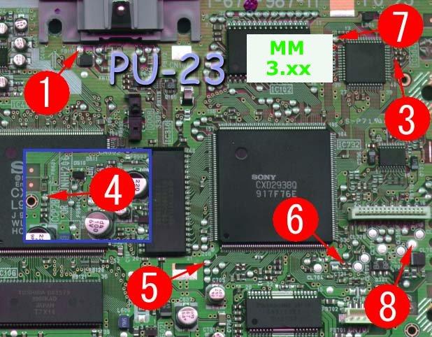
Model No.: SCPH-30001 Ntsc U/C Serial: U4019222 Date Code 1B If u need any other info to figure it out, ask, and ill see what i can tell ya 0 I havnt bought mod chip yet, cause i can figure out what kinds i can use for it. I googled in order to find a soldering diagram for the chip and the board but I was not able to. i need to figure at what kind of modchip, i can use in my 13 ps2. I opened it up in order to clean it a bit and I noticed that one of the modchip wires got loose and it's no longer soldered. Here are some tips I have for you when you are soldering your chip into the PU-23. Hi, so today I dug out my old PS1 for some retro fun (quarantine got me). Since the diagram isn't the clearest I'd like to mention that pin three connects to the left contact on the middle resistor, and pin six connects to the top contact on the left capacitor. Pin four is located towards the top left side of the board.

PU-23 MM3 modchip installation diagramĪbove is the diagram for the PU-23. They also shrunk down the size of the board significantly.įor more information about MM3 chips click here, for more information about PS1 modchips click here.

Download Diagram MODCHIP MATRIX / MODBO 5. The last version of the original PlayStation 1 design was the SCPH-900x. PS2 Slim seri SCPH-90XXX dengan Mainboard GH-072-42 jenis kerusakan GAMBAR CACAT, FREEZE, MACET, HANG, SUARA. The SCPH-9002 is actually just a SCPH-7002.

The SCPH-7003 is actually just a SCPH-5501 V3.0A. The SCPH-5003 is actually just a SCPH-1001 [MD5 CONFIRMED BY BAD_AD84).


 0 kommentar(er)
